
Photovoltaic Systems
Photovoltaic Systems
Display: 127-147 from 630 products
.jpg-817-5663.jpg)
- Brand: Victron Energy
The Inverter RS Smart Solar is a combination of a powerful 48VDC, 6kVA 230VAC inverter and a high voltage, 80-450VDC, 4kW MPPT solar charger. Thanks to its modern design and high frequency technology the inverter only weighs 11kg and has an excellent efficiency, low standby power, and very quiet operation.
The inverter is equipped with a display to read out battery, inverter, and solar charger details. These parameters can also be read out via Bluetooth by the VictronConnect App. In addition to this, the inverter has a VE.Direct and a VE.Can Port, for connection to a GX device for system monitoring.
Inverter RS Smart Solar 48/6000
INVERTER
DC Input voltage range 38 – 64 V
Output Output voltage: 230 VAC ± 2%
Frequency: 50 Hz ± 0.1% (1)
Continuous output power at 25°C Increases linearly from 4800 W at 46 VDC to 5300 W at 52 VDC
Continuous output power at 40°C: 4500W
Continuous output power at 65°C: 3000W
Peak power 9 kW for 3 seconds
Short-circuit output current: 50A
Maximum efficiency: 96.5% at 1 kW load 94% at 5 kW load
SOLAR:
Maximum DC voltage: 450V
Nominal DC voltage: 300V
Start-up voltage: 120V
MPPT operating voltage range 80 – 450V
DC input current limit: 18A
Maximum DC input current: 20A
Maximum PV input power: 4000W
Maximum DC charging power: 4000W
- Brand: Victron Energy
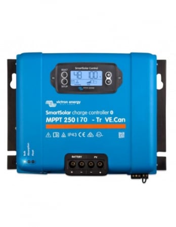
MPPT: Ultra Fast Maximum Power Point Tracking
The MPPT VE.Can SmartSolar charger connects to a PV array of 150 or 250 Volt Voc and will automatically detect and charge your 12, 24, or 48V battery bank with current ranging from 70 to 100A depending on the model.
The charge settings are fully programmable and can even be set up for different battery chemistries, like lead-acid, lithium and others.
Control Your Charger Remotely
The MPPT VE.Can SmartSolar charger can be remotely controlled and configured over Bluetooth via the VictronConnect App. This allows device set-up, management, and at-a-glance information, such as battery voltage and current, PV voltage and current, and historical data.
Daisy Chain Additional Units
The VE.Can SmartSolar charger is equipped with CAN bus ports. This allows for communication with additional VE.Can SmartSolar chargers. The additional units are simply “daisy chained” to each other with a single RJ45 cable between the individual units.
When connected to each other, all individual VE.Can SmartSolar chargers, will synchronise their charge stages. They can also send their data, via a single cable, to a GX monitoring device.
Remote Monitoring and Control
If the GX device is connected to the internet, the Victron Remote Management Portal (VRM) provides access to the full power of your solar charger(s).
SmartSolar Control Display
The VE.Can SmartSolar charger is also equipped with a VE.Direct port like our other MPPT solar chargers. This port can be for single unit monitoring or for streetlight control. The remote on/off connector can be externally controlled by a third-party device like a lithium battery. An optional plug-in LCD display/control provides live-data, set-up and management, straight from the face of the device.
Advanced Maximum Power Point Detection in case of partial shading conditions
If partial shading occurs, two or more maximum power points (MPP) may be present on the power-voltage curve. Conventional MPPTs tend to lock to a local MPP, which may not be the optimum MPP. The innovative SmartSolar algorithm will always maximize energy harvest by locking to the optimum MPP.
Outstanding conversion efficiency
No cooling fan. Maximum efficiency exceeds 98%.
Flexible charge algorithm
Fully programmable charge algorithm, and eight pre-programmed algorithms, selectable with a rotary switch (see manual for details).
Extensive electronic protection
Over-temperature protection and power derating when temperature is high.
PV short circuit and PV reverse polarity protection.
PV reverse current protection.
Bluetooth Smart built-in
The wireless solution to set-up, monitor, update and synchronise SmartSolar Charge Controllers.
Internal temperature sensor and optional external battery voltage and temperature sensing via Bluetooth
A Smart Battery Sense or a BMV-712 Smart Battery Monitor can be used to communicate battery voltage and temperature to one or more SmartSolar Charge Controllers.
VE.Can: the multiple controller solution
Up to 25 units can be synchronised with VE.Can
VE.Direct or VE.Can
For a wired data connection to a Color Control GX, other GX products, PC or other devices
Remote on-off
To connect for example to a VE.BUS BMS.
Programmable relay
Can be programmed to trip on an alarm, or other events.
Optional: SmartSolar pluggable LCD display
Simply remove the rubber seal that protects the plug on the front of the controller, and plug-in the display.
- Brand: Victron Energy
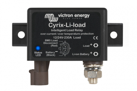
The Cyrix-Li-load will disengage when its control input becomes free floating. If the battery voltage recovers after disconnection (which will happen when no other loads are connected to the battery), the output of the BMS will become high and the Cyrix will reengage after 30 seconds. After 3 attempts to reengage, the Cyrix will remain disengaged until battery voltage has increased to more than 13 V (resp. 26 V or 52 V) during at least 30 seconds (which is a sign that the battery is being recharged). Alternatively, a BatteryProtect can be used (advantage: very low power consumption).
- Brand: Victron Energy
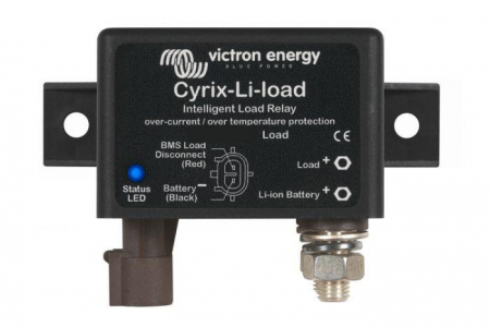
The Cyrix-Li-load will disengage when its control input becomes free floating. If the battery voltage recovers after disconnection (which will happen when no other loads are connected to the battery), the output of the BMS will become high and the Cyrix will reengage after 30 seconds. After 3 attempts to reengage, the Cyrix will remain disengaged until battery voltage has increased to more than 13 V (resp. 26 V or 52 V) during at least 30 seconds (which is a sign that the battery is being recharged). Alternatively, a BatteryProtect can be used (advantage: very low power consumption)
- Brand: Victron Energy
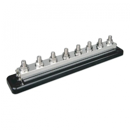
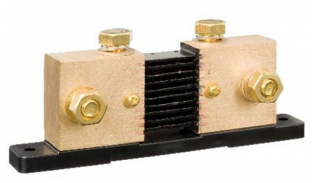
Busbars are used for high current distribution and at the same time they provide connections for batteries and/or DC equipment.
Victron offer a number of busbars with different current ratings, and a different number of connection terminals. Each busbar is fitted out with a removable protection cover.
- Brand: Victron Energy
Shunt 2000A/50mV-0,5 / 3xM10.
- Brand: Victron Energy
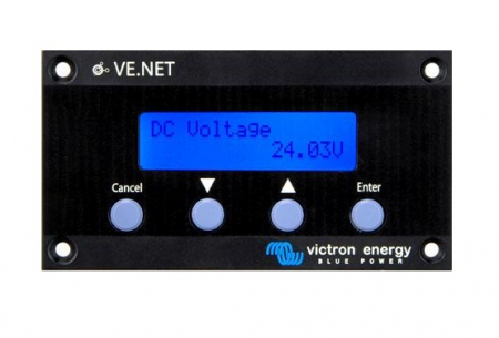
VE.Net GMDSS panel remotely monitors the Victron Skylla-TG GMDSS charger.

- Brand: Victron Energy
The VE.Net Panel provides a user interface to all connected VE.Net devices. This could be one or more VE.Net Battery Controllers, VE.Net Generator Modules, regular Victron Energy equipment such as inverters and the Multi Inverter/Charger combination, or other third party equipment

- Brand: Victron Energy
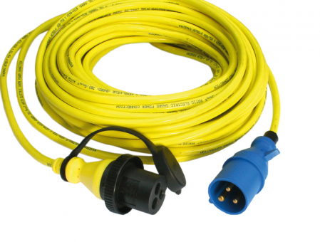
Shore Power Cord 15m 25A/250Vac (3x4sqmm).
- Waterproof Shore Power Cable and Inlet IP56
- Moulded Plug and Connector
- Power indication LED
- Protection Cap

- Brand: Victron Energy
The Blue Power Panel provides intuitive control for all devices connected to the VE.Net network. It can be used to view and configure the full range of settings on VE.Net devices. Furthermore, its fully customizable overview screens make it the ideal monitoring tool for your power system.
The BPP now features an integrated VE.Net to VE.Bus Converter (VVC). This allows you to combine the powerful control of the VE Configure software with the simple interface of the BPP, without requiring a computer or additional interface devices.
BPP2 and BPC GX
The Blue Power Panel 2 and the Blue Power Control GX almost have the same features. The difference between the two models is the design and the mounting of the panel. The body of the GX panel is made of plastic, which makes the panel lighter and adds a modern look to the panel. An extra advantage of the GX panel is the easy mounting: the included mounting frame allows the user to install the panel from either front or back side. Due to the mounting frame, the mounting holes will no longer be visible.

- Brand: Victron Energy
Voltage and Frequency Relay with integrated vector shift relay grid and plant protection.
The SPI1021 monitors voltage and frequency in plants for own generation of electricity. It fulfills the requirements of CEI 0-21. 3 selectable programs allow measuring 3 phases to neutral (4-wire mode), 3 phases phasephase (3-wire mode) and single phase to neutral (2-wire). The SPI1021 can monitor all decentralized power, photovoltaic, wind or thermal plants, that feed in the low voltage and medium voltage grid. In applications with possible asymmetry >6 kVA, power balance has to be monitored extra.
- Brand: Victron Energy
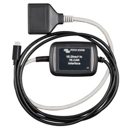
The VE.Direct to VE.CAN interface cable can be used to make BMV-700 information available on a VE.Can network. Where it can be read by a Color Control GX for example.
Limitations
- The interface cable does not work with other VE.Direct products, such as Solar Chargers, Inverters and also not with the BMV-712 Smart.
- When used in combination with a BMV-702 there is limited functionality with regards to the AUX function in the BMV: When used to measure starter battery voltage, that voltage will be transmitted to VE.Can. But when used to measure temperature and or mid-voltage, that data will not be transmitted on the VE.Can network.
- Brand: Victron Energy
Shore Power Cord 25m 16A/250Vac (3×2.5sqmm)
- Brand: Victron Energy
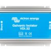
The galvanic isolator consists internally of two diodes which are connected in anti-parallel fashion. When they are connected in this way, the diodes allow current in both directions but only above a certain threshold voltage. The voltage at which diodes conduct is about 1.4 Vdc.
The isolator is installed directly behind your boat’s 230V connection. The forward voltage from the galvanic isolator is higher than the potential difference between metals. As a result, this voltage will not allow conduction and as such, the galvanic isolator will prevent any electrolytic current. However, if there is a (higher) error voltage in the AC circuit, the diodes will allow current through and the residual-current device will break the circuit.
- Brand: Victron Energy
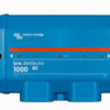
A modular DC bus bar, with locations for four DC fuses. It will monitor the status of each fuse, and indicate its condition with a LED on the front. Part of the modular Lynx distribution system.
Contains a positive and negative bus-bar and provides a connection for 4 individual DC equipment circuits, loads or DC groups. It has a space for individual DC fuses per DC group.
There is an optional feature of an LED for each fuse to indicate if fuse is blown.
If you wish to use the fuse indication LEDs on the Lynx Distributor, it also requires a connection to a Lynx Shunt. The Lynx Shunt contains the necessary wide input (8 to 70VDC) power supply to output the required 5V (4,5V-5,5V) power requirement of the Lynx Distributor circuit board.
RJ11 fly leads are used to connect the Lynx Shunt to the Distributor. This RJ11 cable is supplied with the Distributor in the box. There are two ports on the Lynx Shunt, and it is possible to use either.
When all is OK, only the central LED is green; when a fuse has blown (or is missing) the central and blow fuse circuit LEDs turn red. If you are not using all connection points in your DC distribution, it may be necessary to fit dummy fuses to extinguish the red LEDs.
A future upgrade is planned to also send info back to the GX device over the VE-can, but is not yet implemented.

- Brand: Victron Energy
This NMEA2000 drop cable makes the BMV-700 information available to an NMEA2000 networks. Battery information such as voltage, current and state of charge can be displayed on common purpose displays from other manufacturers which accept the NMEA2000 data being sent.
Limitations:
- The cable does not work with other VE.Direct products, such as Solar Chargers, Inverters and also not with the BMV-712 Smart.
- When used in combination with a BMV-702 there is limited functionality with regards to the AUX function in the BMV: When used to measure starter battery voltage, that voltage will be transmitted to the NMEA2000 network. But when used to measure temperature and or mid-voltage, that data will not be transmitted on the NMEA2000 network.
- Brand: Victron Energy
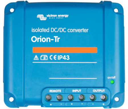
Remote on-off
The remote on-off eliminates the need for a high current switch in the input wiring. The remote on-off can be operated with a low power switch or by for example the engine run/stop switch (see manual).
Adjustable output voltage: can also be used as a battery charger
For example to charge a 12 Volt starter or accessory battery in an otherwise 24V system.
All models are short circuit proof and can be paralleled to increase output current
An unlimited number of units can be connected in parallel.
IP43 protection
When installed with the screw terminals oriented downwards.
Screw terminals
No special tools needed for installation.
Input fuse
On 12V and 24V input models only.

- Brand: Victron Energy
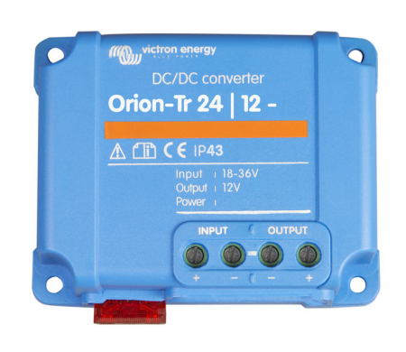
Remote on-off
The remote on-off eliminates the need for a high current switch in the input wiring. The remote on-off can be operated with a low power switch or by for example the engine run/stop switch (see manual).
Adjustable output voltage: can also be used as a battery charger
For example to charge a 12 Volt starter or accessory battery in an otherwise 24V system.
All models are short circuit proof and can be paralleled to increase output current
An unlimited number of units can be connected in parallel.
IP43 protection
When installed with the screw terminals oriented downwards.
Screw terminals
No special tools needed for installation.
Input fuse
On 12V and 24V input models only.
- Brand: Victron Energy
Remote on-off
The remote on-off eliminates the need for a high current switch in the input wiring. The remote on-off can be operated with a low power switch or by for example the engine run/stop switch (see manual).
Adjustable output voltage: can also be used as a battery charger
For example to charge a 12 Volt starter or accessory battery in an otherwise 24V system.
All models are short circuit proof and can be paralleled to increase output current
An unlimited number of units can be connected in parallel.
IP43 protection
When installed with the screw terminals oriented downwards.
Screw terminals
No special tools needed for installation.
Input fuse
On 12V and 24V input models only.