
Accessories
Display: 1-24 from 72 products
your selection:
Manufacturer: Victron Energy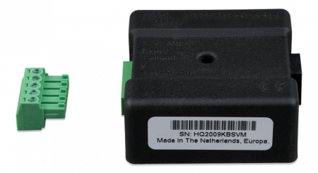
- Brand: Victron Energy
The CAN-bus Temp. Sensor is a battery temperature sensor for the Buck-Boost DC/DC converter range and is an essential accessory when the Buck-Boost DC/DC converter is connected to a LFP lithium battery.
Temperature sensing is needed when LFP lithium batteries are charged at low temperatures. The charge current to a lithium battery has to be reduced once the battery temperature drops below 5 degrees and the charge current has to stop when the temperature drops below zero.
The CAN-bus Temp. Sensor takes care of this. It measures the lithium battery temperature and sends this to the Buck-Boost DC/DC converter. The Buck-Boost DC/DC converter will reduce or stop charge when the battery temperature drops too low.
In addition to this, the CAN-bus Temp. Sensor can also be connected to the temperature sensor terminal in a Multi or Quattro, so the Multi or Quattro can reduce or stop charging when the battery temperature drops too low.

- Brand: Victron Energy
The BatteryProtect disconnects the battery from non essential loads before it is completely discharged (which would damage the battery) or before it has insufficient power left to crank the engine.
The BatteryProtect is not designed for reverse currents from charging sources
Programming made easy
The BatteryProtect can be set to engage / disengage at several different voltages.
The seven segment display will indicate which setting has been chosen.
A special setting for Li-ion batteries
In this mode the Battery Protect can be controlled by the VE.Bus BMS.
Ultra-low current consumption
This is important in case of Li-ion batteries, especially after low voltage shutdown.
Please see our Li-ion battery datasheet and the VE.Bus BMS manual for more information.
Over voltage protection
To prevent damage to sensitive loads due to over voltage, the load is disconnected whenever the DC voltage exceeds 64 V.
Ignition proof
No relays but MOSFET switches, and therefore no sparks.
Delayed alarm output
The alarm output is activated if the battery voltage drops below the preset disconnect level during more than 12 seconds. Starting the engine will therefore not activate the alarm. The alarm output is a short circuit proof open collector output to the negative (minus) rail, max. current 50 mA. The alarm output is typically used to activate a buzzer, LED or relay.
Delayed load disconnect and delayed reconnect
The load will be disconnected 90 seconds after the alarm has been activated. If the battery voltage increases again to the connect threshold within this time period (after the engine has been started for example), the load will not be disconnected.
The load will be reconnected 30 seconds after the battery voltage has increased to more than the preset reconnect voltage.
- Brand: Victron Energy
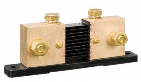
Shunt 2000A/50mV-0,5 / 3xM10.
- Brand: Victron Energy
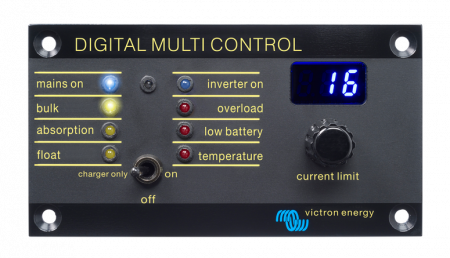
This panel is intended both for Multis and Quattros. It allows PowerControl and PowerAssist current limit setting for two AC sources: a generator and shore side current for example. Setting range: up to 200 Amps. The brightness of the LEDs is automatically reduced during night time.
- Brand: Victron Energy
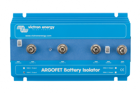
Similarly to diode battery isolators, FET isolators allow simultaneous charging of two or more batteries from one alternator (or a single output battery charger), without connecting the batteries together. Discharging the accessory battery for example will not result in also discharging the starter battery.
In contrast with diode battery isolators, FET isolators have virtually no voltage loss. Voltage drop is less than 0,02 Volt at low current and averages 0,1 Volt at higher currents. When using ARGO FET Battery Isolators, there is no need to also increase the output voltage of the alternator. Care should taken however to keep cable lengths short and of sufficient cross section.
Example:
When a current of 100 A flows through a cable of 50 mm> cross section (AWG 0) and 10 m length (30 ft), the voltage drop over the cable will be 0,26 Volt. Similarly a current of 50 A through a cable of 10 mm> cross section (AWG 7) and 5 m length (15 ft) will result in a voltage drop of 0,35 Volt!
Alternator energize input
Some alternators need DC voltage on the B+ output to start charging. Obviously, DC will be present when the alternator is directly connected to a battery. Inserting a Diode or FET splitter will however prevent any return voltage/current from the batteries to the B+, and the alternator will not start. The new Argofet isolators have a special current limited energize input that will power the B+ when the engine run/stop switch is closed.
- Brand: Victron Energy
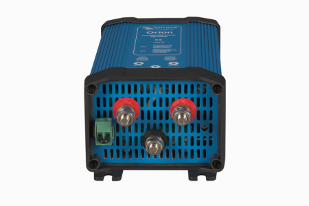
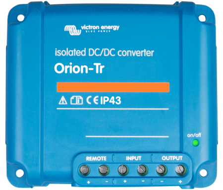
The Orion-Tr Smart DC-DC charger is a professional DC to DC adaptive 3-stage charger with built-in Bluetooth.
For use in dual battery systems in vehicles or on boats where the (smart) alternator and the start battery are used to charge the service battery. The unit can be monitored and programmed via Bluetooth and can be remotely controlled via a remote on/off switch and has an engine running detection mechanism.
The Orion Tr-Smart charger can be used in 12V or 24V systems and is suitable for both lead acid and lithium batteries. Models are available up to 400W and unlimited multiple units can be connected in parallel to increase output power.
Suitable for high temperatures up to 55°C with a full rated output up to 40°C.
Bluetooth Smart enabled
Any Bluetooth enabled smart phone, tablet or other device can be used to monitor, to change settings and to update the charger when new software features become available.
Fully programmable
– Battery charge algorithm (configurable) or fixed output.
– Smart alternator compatibility: engine running detection mechanism.
Adaptive 3-stage charge algorithm: bulk – absorption – float
- For lead acid batteries it is important that during shallow discharges the absorption time is kept short in order to prevent overcharging of the battery. After a deep discharge the absorption time is automatically increased to make sure that the battery is completely recharged.
- For lithium batteries absorption time is fixed, default 2 hours.
- Alternatively, a fixed output voltage can be chosen.
Remote on-off
A remote on/off switch or relay contact can be connected to a two-pole connector.
Alternatively, the H terminal (right) of the two-pole connector can be switched to battery plus, or the L terminal (left) of the two pole connector can be switched to battery minus (or the chassis of a vehicle, for example).
All models are short circuit proof and can be paralleled to increase output current
An unlimited number of units can be connected in parallel.
High temperature protected
The output current will reduce at high ambient temperature.
Screw terminals
No special tools needed for installation.
Input fuse (not replaceable)
- Brand: Victron Energy
VE.Net GMDSS panel remotely monitors the Victron Skylla-TG GMDSS charger.

- Brand: Victron Energy
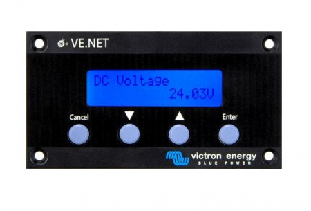
The VE.Net Panel provides a user interface to all connected VE.Net devices. This could be one or more VE.Net Battery Controllers, VE.Net Generator Modules, regular Victron Energy equipment such as inverters and the Multi Inverter/Charger combination, or other third party equipment
- Brand: Victron Energy

- Brand: Victron Energy
The Blue Power Panel provides intuitive control for all devices connected to the VE.Net network. It can be used to view and configure the full range of settings on VE.Net devices. Furthermore, its fully customizable overview screens make it the ideal monitoring tool for your power system.
The BPP now features an integrated VE.Net to VE.Bus Converter (VVC). This allows you to combine the powerful control of the VE Configure software with the simple interface of the BPP, without requiring a computer or additional interface devices.
BPP2 and BPC GX
The Blue Power Panel 2 and the Blue Power Control GX almost have the same features. The difference between the two models is the design and the mounting of the panel. The body of the GX panel is made of plastic, which makes the panel lighter and adds a modern look to the panel. An extra advantage of the GX panel is the easy mounting: the included mounting frame allows the user to install the panel from either front or back side. Due to the mounting frame, the mounting holes will no longer be visible.
- Brand: Victron Energy
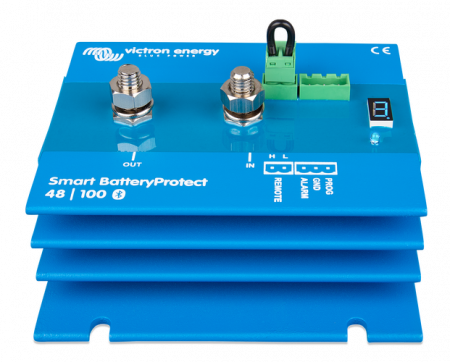
Protects the battery against excessive discharge and can be used as a system on/off switch
The Smart BatteryProtect disconnects the battery from non-essential loads before it is completely discharged (which would damage the battery) or before it has insufficient power left to crank the engine.
The Smart BatteryProtect can also be used as a system on/off switch. See manual for details.
Bluetooth: programming made easy
When using Bluetooth to program the Smart BatteryProtect any required engage/disengage levels can be set.
Alternatively, one of nine predefined engage/disengage levels can be set with the programming pin (see manual).
If required, Bluetooth can be disabled.
A special setting for Li-ion batteries
In this mode the Battery Protect can be controlled by the VE.Bus BMS.
Note: the BatteryProtect can also be used as a charge interrupter in between a battery charger and a Li-ion battery. See connection
diagram in the manual.
Ultra-low current consumption
This is important in case of Li-ion batteries, especially after low voltage shutdown.
Please see our Li-ion battery datasheet and the VE.Bus BMS manual for more information.
Over voltage protection
To prevent damage to sensitive loads due to over voltage, the load is disconnected whenever the DC voltage exceeds 64V.
Ignition proof
No relays but MOSFET switches, and therefore no sparks.
Delayed alarm output
The alarm output is activated if the battery voltage drops below the preset disconnect level during more than 12 seconds. Starting the engine will therefore not activate the alarm. The alarm output is a short circuit proof open collector output to the negative (minus) rail, max. current 50 mA. The alarm output is typically used to activate a buzzer, LED or relay.
Delayed load disconnect and delayed reconnect
The load will be disconnected 90 seconds after the alarm has been activated. If the battery voltage increases again to the connect threshold within this time period (after the engine has been started for example), the load will not be disconnected.
The load will be reconnected 30 seconds after the battery voltage has increased to more than the preset reconnect voltage.
- Brand: Victron Energy
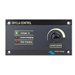
The Skylla Control allows you to alter the charge current and see the system status.
- Brand: Victron Energy
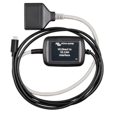
The VE.Direct to VE.CAN interface cable can be used to make BMV-700 information available on a VE.Can network. Where it can be read by a Color Control GX for example.
Limitations
- The interface cable does not work with other VE.Direct products, such as Solar Chargers, Inverters and also not with the BMV-712 Smart.
- When used in combination with a BMV-702 there is limited functionality with regards to the AUX function in the BMV: When used to measure starter battery voltage, that voltage will be transmitted to VE.Can. But when used to measure temperature and or mid-voltage, that data will not be transmitted on the VE.Can network.
- Brand: Victron Energy
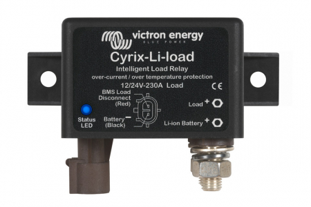
The Cyrix-Li-load will disengage when its control input becomes free floating. If the battery voltage recovers after disconnection (which will happen when no other loads are connected to the battery), the output of the BMS will become high and the Cyrix will reengage after 30 seconds. After 3 attempts to reengage, the Cyrix will remain disengaged until battery voltage has increased to more than 13 V (resp. 26 V or 52 V) during at least 30 seconds (which is a sign that the battery is being recharged). Alternatively, a BatteryProtect can be used (advantage: very low power consumption).
- Brand: Victron Energy
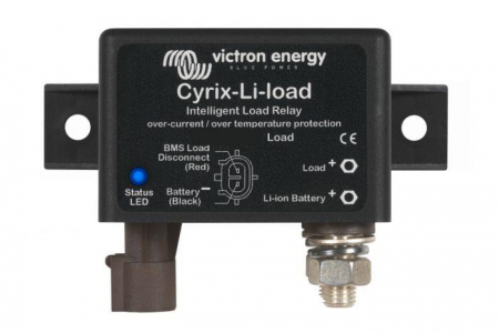
The Cyrix-Li-load will disengage when its control input becomes free floating. If the battery voltage recovers after disconnection (which will happen when no other loads are connected to the battery), the output of the BMS will become high and the Cyrix will reengage after 30 seconds. After 3 attempts to reengage, the Cyrix will remain disengaged until battery voltage has increased to more than 13 V (resp. 26 V or 52 V) during at least 30 seconds (which is a sign that the battery is being recharged). Alternatively, a BatteryProtect can be used (advantage: very low power consumption)
- Brand: Victron Energy
The LiFePO4 battery: preventing cell under voltage, overvoltage and over temperature
The first line of protection is cell balancing. All Victron LiFePO4 batteries have integrated cell balancing.
The second line of protection consists of:
– shut down of the load in case of imminent cell under voltage, and
– shut down or reduction of the charging current in case of imminent cell over voltage, high temperature
(>50°C) or low temperature (<0°C).
The VE.Bus BMS is the core of the second protection line.
However, not all loads or chargers can be controlled directly by the VE.Bus BMS.
In order to shut down such loads or chargers several VE.Bus BMS controllable Cyrix switches are available.
Cyrix-Li-load
The Cyrix-Li-load will disengage when its control input becomes free floating.
If the battery voltage recovers after disconnection (which will happen when no other loads are connected to the battery), the output of the BMS will become high and the Cyrix will reengage after 30 seconds. After 3 attempts to reengage, the Cyrix will remain disengaged until battery voltage has increased to more than 13 V (resp. 26 V or 52 V) during at least 30 seconds (which is a sign that the battery is being recharged).
Alternatively, a BatteryProtect can be used (advantage: very low power consumption).
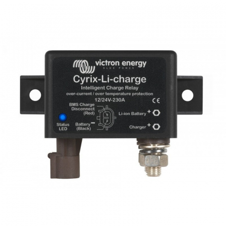
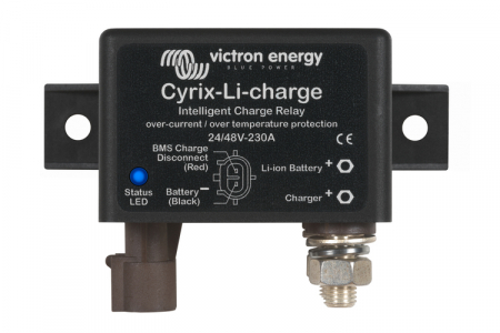
Cyrix-Li-Charge
The Cyrix-Li-Charge will connect a battery charger with 3 seconds delay:
– if the charge disconnect output of the VE.Bus BMS is high, and
– if it senses 13,7 V (resp. 27,4 V or 54,8 V) or more on its battery charger connection terminal, and
– if it senses 2 V or more on its battery terminal (the Cyrix will remain open if not connect to the battery).
The Cyrix-Li-Charge will disengage immediately whenever its control input becomes free floating, signalling cell over
voltage or cell over temperature.
In general a cell over voltage alarm will reset shortly after charging has been stopped. The Cyrix will then reconnect the charger after a delay 3 seconds. After 2 attempts to reengage with 3 seconds delay, the delay increases to 10 minutes.
Whenever battery voltage is less than 13,5 V (resp. 27 V or 54 V), the Cyrix will disengage with a delay of 1 hour.
Note 1: In case of zero discharge current, or a small discharge current, the Cyrix will not disengage shortly after the
charger has been switched off and/or disconnected, because battery voltage will remain higher than 13,5 V.
Note 2: If, after the Cyrix has disengaged, the output of the battery charger immediately increases to 13,7 V or more, the
Cyrix will reengage, with 3 seconds delay.
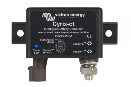
Cyrix-Li-ct
The functionality of the Cyrix-Li-ct is analogous to the Cyrix-ct.
The Cyrix-Li-ct will parallel connect a lead acid starter battery and a LiFePO4 battery:
– if the charge disconnect output of the VE.Bus BMS is high, and
– if it senses 13,4 V (resp. 26,8 V) or more on one of its power terminals.
The Cyrix will disengage immediately:
– when its control output becomes free floating, signalling cell over voltage or cell over temperature, and/or
– when battery voltage drops below 13,2 V.
Start assist function: a short positive pulse will close the relay during 30 seconds (see figure on page 2).
A built-in transient voltage suppressor will limit the voltage spike that may occur when the Cyrix suddenly disengages due to cell overvoltage or over temperature.
LED status indication
LED on: engaged LED 10 s flash: disengaged
LED 2 s flash: connecting LED 2 s blink: disconnecting
LED 0,25 s blink: alarm (over temperature; voltage > 16 V; both batteries < 10 V; one battery < 2 V)
(multiply by two for 24 V)
- Brand: Victron Energy
The LiFePO4 battery: preventing cell under voltage, overvoltage and over temperature
The first line of protection is cell balancing. All Victron LiFePO4 batteries have integrated cell balancing.
The second line of protection consists of:
– shut down of the load in case of imminent cell under voltage, and
– shut down or reduction of the charging current in case of imminent cell over voltage, high temperature
(>50°C) or low temperature (<0°C).
The VE.Bus BMS is the core of the second protection line.
However, not all loads or chargers can be controlled directly by the VE.Bus BMS.
In order to shut down such loads or chargers several VE.Bus BMS controllable Cyrix switches are available.
Cyrix-Li-load
The Cyrix-Li-load will disengage when its control input becomes free floating.
If the battery voltage recovers after disconnection (which will happen when no other loads are connected to the battery), the output of the BMS will become high and the Cyrix will reengage after 30 seconds. After 3 attempts to reengage, the Cyrix will remain disengaged until battery voltage has increased to more than 13 V (resp. 26 V or 52 V) during at least 30 seconds (which is a sign that the battery is being recharged).
Alternatively, a BatteryProtect can be used (advantage: very low power consumption).
Cyrix-Li-Charge
The Cyrix-Li-Charge will connect a battery charger with 3 seconds delay:
– if the charge disconnect output of the VE.Bus BMS is high, and
– if it senses 13,7 V (resp. 27,4 V or 54,8 V) or more on its battery charger connection terminal, and
– if it senses 2 V or more on its battery terminal (the Cyrix will remain open if not connect to the battery).
The Cyrix-Li-Charge will disengage immediately whenever its control input becomes free floating, signalling cell over
voltage or cell over temperature.
In general a cell over voltage alarm will reset shortly after charging has been stopped. The Cyrix will then reconnect the charger after a delay 3 seconds. After 2 attempts to reengage with 3 seconds delay, the delay increases to 10 minutes.
Whenever battery voltage is less than 13,5 V (resp. 27 V or 54 V), the Cyrix will disengage with a delay of 1 hour.
Note 1: In case of zero discharge current, or a small discharge current, the Cyrix will not disengage shortly after the
charger has been switched off and/or disconnected, because battery voltage will remain higher than 13,5 V.
Note 2: If, after the Cyrix has disengaged, the output of the battery charger immediately increases to 13,7 V or more, the
Cyrix will reengage, with 3 seconds delay.
Cyrix-Li-ct
The functionality of the Cyrix-Li-ct is analogous to the Cyrix-ct.
The Cyrix-Li-ct will parallel connect a lead acid starter battery and a LiFePO4 battery:
– if the charge disconnect output of the VE.Bus BMS is high, and
– if it senses 13,4 V (resp. 26,8 V) or more on one of its power terminals.
The Cyrix will disengage immediately:
– when its control output becomes free floating, signalling cell over voltage or cell over temperature, and/or
– when battery voltage drops below 13,2 V.
Start assist function: a short positive pulse will close the relay during 30 seconds (see figure on page 2).
A built-in transient voltage suppressor will limit the voltage spike that may occur when the Cyrix suddenly disengages due to cell overvoltage or over temperature.
LED status indication
LED on: engaged LED 10 s flash: disengaged
LED 2 s flash: connecting LED 2 s blink: disconnecting
LED 0,25 s blink: alarm (over temperature; voltage > 16 V; both batteries < 10 V; one battery < 2 V)
(multiply by two for 24 V)

- Brand: Victron Energy
The Smart BMS CL 12/100 is a Battery Management system for Victron lithium-iron-phosphate (LiFePO4) Smart Batteries. It has been specifically designed for 12V systems with a 12V alternator.
The BMS CL 12/100 monitors and protects each individual battery cell within the battery (or battery bank) and will disconnect the alternator, charge sources or DC loads in case of low battery voltage, high battery voltage or over temperature.
The dedicated alternator input provides current limiting and one-way traffic from the alternator into the battery, this so any size alternator (and start battery) can be safely connected to the Smart Lithium battery or batteries.
The BMS is also equipped with a remote on off connector, to turn the BMS (and the system) off via a remote switch, and a pre-alarm contact, to give a warning signal before the BMS will disconnect the batteries from the system.
- Brand: Victron Energy
Remote on-off
The remote on-off eliminates the need for a high current switch in the input wiring. The remote on-off can be operated with a low power switch or by for example the engine run/stop switch (see manual).
Adjustable output voltage: can also be used as a battery charger
For example to charge a 12 Volt starter or accessory battery in an otherwise 24V system.
All models are short circuit proof and can be paralleled to increase output current
An unlimited number of units can be connected in parallel.
IP43 protection
When installed with the screw terminals oriented downwards.
Screw terminals
No special tools needed for installation.
Input fuse
On 12V and 24V input models only.

- Brand: Victron Energy
This NMEA2000 drop cable makes the BMV-700 information available to an NMEA2000 networks. Battery information such as voltage, current and state of charge can be displayed on common purpose displays from other manufacturers which accept the NMEA2000 data being sent.
Limitations:
- The cable does not work with other VE.Direct products, such as Solar Chargers, Inverters and also not with the BMV-712 Smart.
- When used in combination with a BMV-702 there is limited functionality with regards to the AUX function in the BMV: When used to measure starter battery voltage, that voltage will be transmitted to the NMEA2000 network. But when used to measure temperature and or mid-voltage, that data will not be transmitted on the NMEA2000 network.
- Brand: Victron Energy
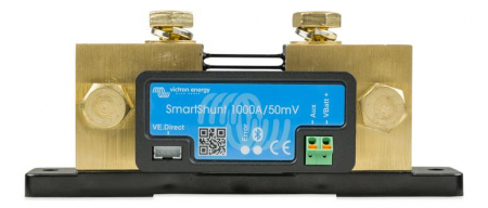
The SmartShunt is an all in one battery monitor, only without a display. Your phone acts as the display. The SmartShunt connects via Bluetooth to the VictronConnect App on your phone (or tablet) and you can conveniently read out all monitored battery parameters, like state of charge, time to go, historical information and much more.
Alternatively the SmartShunt can be connected and be read by a GX device. Connection to the SmartShunt is made via a VE.Direct cable.
The SmartShunt is a good alternative for a BMV battery monitor, especially for systems where battery monitoring is needed but less wiring and clutter is wanted. The SmartShunt is equipped with Bluetooth, a VE.Direct port and a connection that can be used for: monitoring a second battery, midpoint monitoring or a temperature sensor.
- Brand: Victron Energy
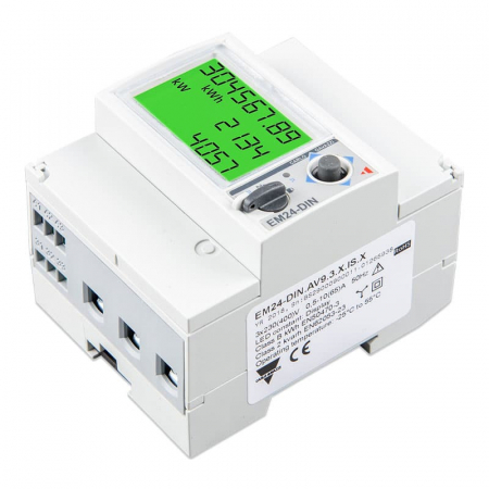
The EM24 is for 3 phase monitoring only.
To measure the power and energy of the whole application at the distribution box. Or to measure the output of a PV Inverter, to display the data on the Color Control GX.
The Energy Meter can be used as a:
- Grid meter, and used as control input for an ESS System.
- Measure the output of a PV Inverter
- Measure the output of a AC Genset
- Brand: Victron Energy
Remote on-off
The remote on-off eliminates the need for a high current switch in the input wiring. The remote on-off can be operated with a low power switch or by for example the engine run/stop switch (see manual).
Adjustable output voltage: can also be used as a battery charger
For example to charge a 12 Volt starter or accessory battery in an otherwise 24V system.
All models are short circuit proof and can be paralleled to increase output current
An unlimited number of units can be connected in parallel.
IP43 protection
When installed with the screw terminals oriented downwards.
Screw terminals
No special tools needed for installation.
Input fuse
On 12V and 24V input models only.